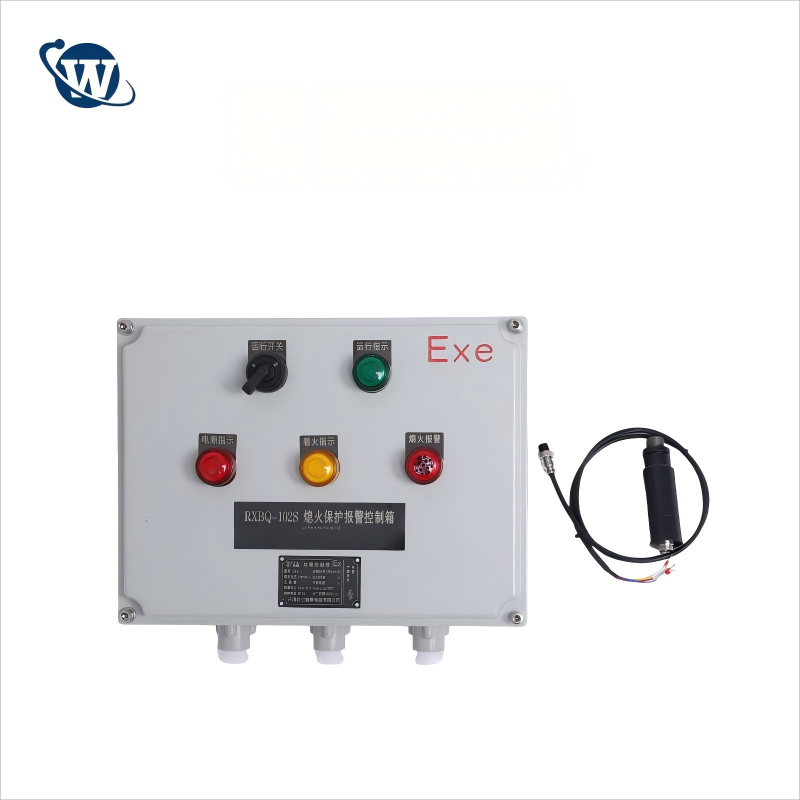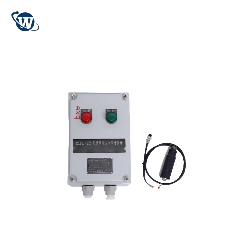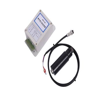
Integrated UV flame detector

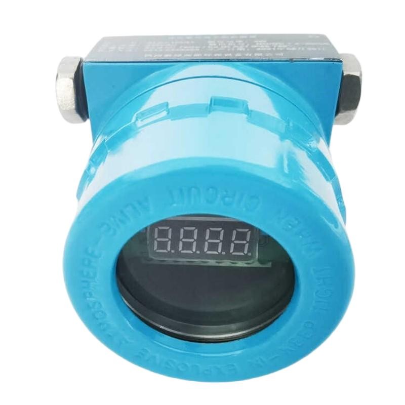
Integrated UV flame detector
RXZJ- 102 | RXZJ-102A | UV-01 | RXFZJ-102 | RXFZJ-102A | RXZJ-102T | RXZJ-102AT | RXZJ-103AT | |
Operating voltage | 220VIA C ±10% | 24V/DC | 24V/DC | 220V/AC ±10% | 220VIAC ±10% | 220V/AC ±10% | 24V/DC | 24V/DC |
switchin g value | 4-20mA switching value | 4-20mA switching value | switching value | 4-20mA switching value | switching value | 4-20mA switching value | 4-20mA switching value | |
Module volume | 155*90*5 5 | 198*90*45 | 75*22*105 | 300*200*150 | 300*200*150 | Spec | Spec | Spec |
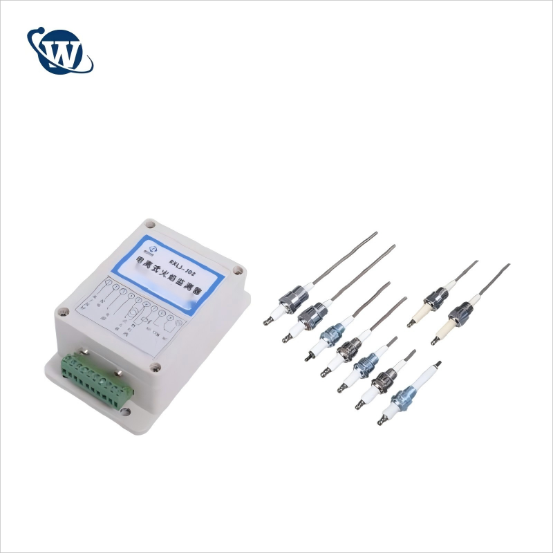
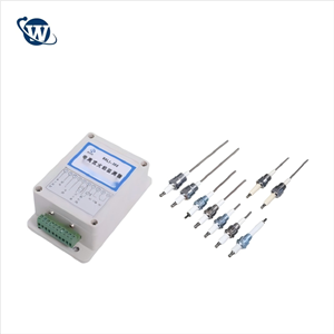
Detecti on probe | Split probe installation thread M20*1.5 (external thread I) body probe installation thread G1 (internal thread) | |||||||
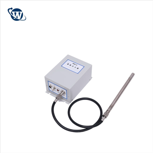
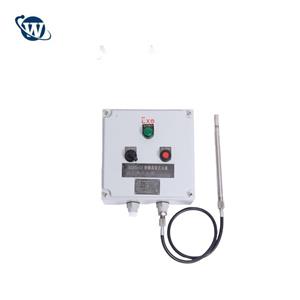
Type | Split ordinarytype | Splitexplosion proof type | Integrated ultraviolet flame monitor with explosion-proof | |||||
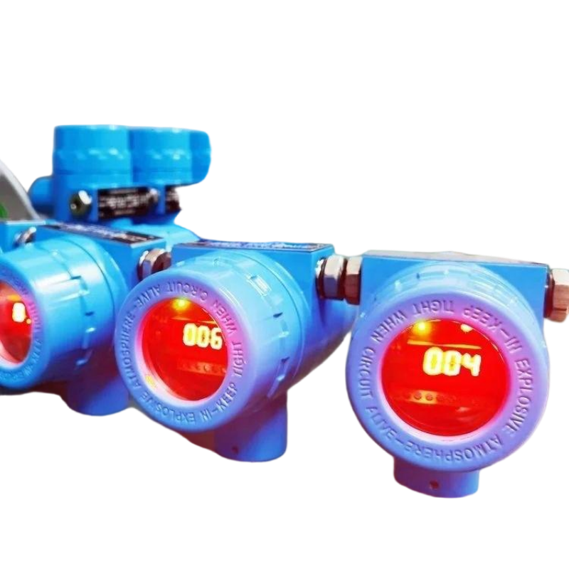
The key components of this flame monitor are all imported components . For example , the ultraviolet photosensitive tube adopts theHamamatsu brand imported from Japan, and the internal chip adopts the ST brand imported from the United States .
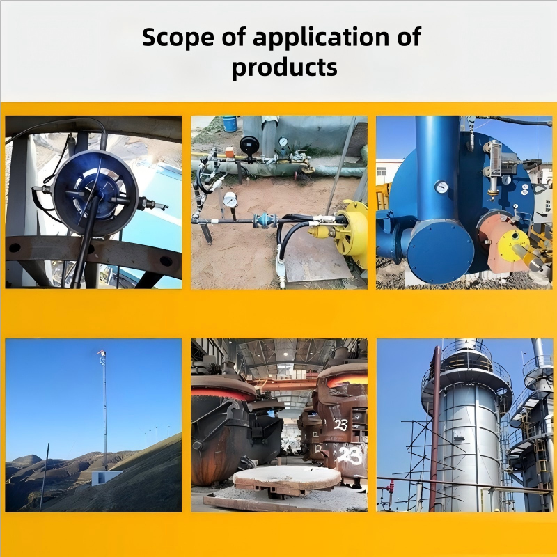
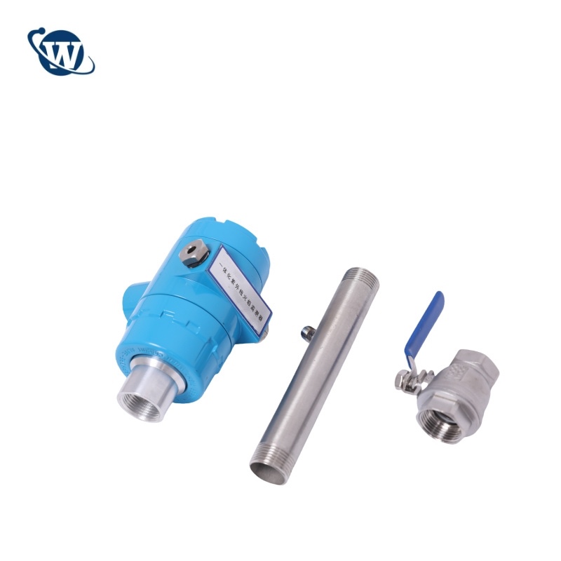
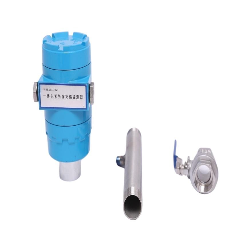
The fire monitoring probe adopts the installation method of external inspection. The installation structure is as follows:
Design of installation structure.
According to Party B's manufacturing fire inspection and installation experience and the form of the supporting heating furnace for this project, it is determined that the installation accessories of the fire inspection probe include: air pipes, ball
valve parts, etc.
De tec tor | 1 | Instrument name | Flame monitor | ||
2 | Quantity | Set | |||
3 | Model | RXZJ-102AT | Type | Ultraviolet sensor | |
4 | Applicable temperature | -20~80℃ | Response time | 1s~6s adjusted | |
5 | Measuring elements | Ultraviolet | Maximum scopeof observation | 120°observation range | |
6 | Security level | SIL3 | Spectral range | 190-280nm | |
7 | Form of process connection | Whorl | Connection size | G" 1 thread | |
8 | Explosion-proof grade | ExdIICT6 | Level of protection | IP66 | |
9 | Shell material | Die-cast aluminum | |||
Tra ns mit ter uni t | 10 | Model | Integration | ||
11 | Type | The transmission unit is integrated with the probe | |||
12 | Installation method | Integrated installation | |||
13 | Applicable temperature | -20~80℃ | |||
14 | Fuel type setting | Fuel gas | |||
15 | Power supply | DC24V | |||
16 | Power | 5W | |||
17 | With or without flamerelay output | With | |||
18 | Analogue signal | 4-20mA | |||
19 | Flame response time | 0.2~10s | |||
20 | No flame response time | 0.2~4s | |||
21 | Electrical interface | G1/2" | |||
Att ach me nt | 22 | Air blowing device | With | ||
23 | Mounting bracket | With | |||
24 | Panel | With display | |||